This is another 100 watt inverter circuit diagram. Built based on IC CD4047 and Mosfet IRF540, this inverter have ability to supply electronic device -which […]
Electronic Schematic Diagram
300Watt Inverter DC 24V to AC 220V
This is the 300W inverter circuit which capable to convert 24VDC become 220VAC. With this circuit, you will have 220V AC power with 300W max […]
50 Watt Power Audio Amplifier
Here the circuit diagram of 50W power amplifier. The amplifier uses a pair of power transistors that are MJ2955 and 2N3055 to amplify the input […]
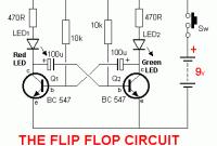
Analog Flip-Flop
Here the analog flip-flop circuit which built based on 2 transistors work as switch. This is very easy made and very cheap circuit. You can […]
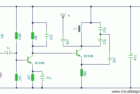
Mini AM Transmitter
This is the simple and low cost AM transmitter schematic diagram built using transistor BC109C. The circuit is in two halfs, an audio amplifier and […]
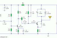
Mini FM Transmitter with 2 Transistors
Here the simple and low cost FM transmitter which powered using two transistors. This circuit may be tuned to operate over the range 87-108MHz with […]
Stereo Electret Mic Preamplifier
This a simple stereo electret microphone pre amplifier circuit. The below design diagram is the design for single channel, but the design of PCB layout […]
5W Tube Amplifier with EL84
Here is the circuit diagram of the classic 5W Tube Amplifier with EL84 as the final amplification component. This is a single channel amplifier (mono) […]
35W Tube Power Amplifier with EL34
This is the circuit diagram of 35W Tube Power Amplifier with EL34. This tube amplifier designed in 1953 and worked from 1954 until 1989. If […]
50W Inverter 12VDC to 220VAC
This is the inverter circuit which capable to convert 12V DC to 220V AC dan handle about 50 Watts small electronic appliances. With this circuit, […]


