The following diagram is the 50W offline switching power supply circuit design. The circuit powered by a MOSFET. BUZ80A/IXTP4N8 for 220V AC voltage input and […]
Category: Power Electronics
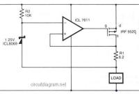
Safe Constant Current Source
In the above circuit diagram, a CMOS operational amplifier (op-amp) controls the current via a P-Channel HEXFET power transistor (IRF9520) to maintain a constant voltage […]
3A Switching Voltage Regulator based LM317HV
Above circuit diagram is a easy, simple and cheap switching voltage regulator which has capability to deliver adjustable voltage output range of 1.8V to 32V […]
PNP Boost for Positive Voltage Regulator
This is the positive voltage regulator circuit with PNP Boost transistor: The IC8211 presents the voltage reference and regulator amplifier, while Q1 will be the […]
Low Forward-Drop Rectifier
This is the circuit diagram of low forward-drop rectifier. A TMOS power FET (Q1) and a LM393 comparator provide a high-efficiency rectifter circuit. When VA […]
100W Inverter 12VDC to 220VAC
The following diagram is an inverter circuit which will give you 220V AC 50Hz with maximum power output of 100W. This inverter built using transistors […]
Solid State Relay
This is the circuit diagram of solid state relay. In reality, it is not a relay after all. There’s no ‘relay’ found, just the electronics […]
12V Lead-Acid Battery Monitor
This easy circuit makes it possible to monitor the charging process to a higher level. Final adjustsments are simple and easy and the only device required is a digital voltmeter for the important accuracy and reliability. Connect an input voltage of 12.65 volt between the positive and negative poles and adjust the 10K trimmer potentiometer until Led 10 lights up.
Automatic 9V Battery Charger
This is the scheme diagram of automatic 9V battery charger circuit, the parts list provided below the schematic image. The circuit was designed by Jan […]
6A / 0-28V Variable Power Supply
The following diagram is the schematic diagram of variable power supply which will deliver 0 to 28V output voltage at 6A or 8A electric current. […]


