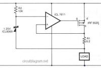
In the above circuit diagram, a CMOS operational amplifier (op-amp) controls the current via a P-Channel HEXFET power transistor (IRF9520) to maintain a constant voltage […]
Category: Misc
Load Cell Amplifier
I’ve found some interesting schematic of load cell amplifier. As we know, load cell amplifier is pretty expensive with fair price range of 100-300 USD. […]
Solid State Relay
This is the circuit diagram of solid state relay. In reality, it is not a relay after all. There’s no ‘relay’ found, just the electronics […]
12V Lead-Acid Battery Monitor
This easy circuit makes it possible to monitor the charging process to a higher level. Final adjustsments are simple and easy and the only device required is a digital voltmeter for the important accuracy and reliability. Connect an input voltage of 12.65 volt between the positive and negative poles and adjust the 10K trimmer potentiometer until Led 10 lights up.
Simple Electronic Combination Lock
The following diagram is a very easy and simple electronic combination lock based on IC LS7220. Component Part List: C1 = 1uF 25V C2 = […]
Adjustable Sine/Square Wave Oscillator
The following scheme diagram is the circuit diagram of simple easily tuned / adjustable sine and square wave oscillator. With this circuit you can easily […]
220V Touch Switch
This is a circuit of a touch switch used to turn on and turn off the electronic device that is connected to the 220V home […]
Insect Repellent
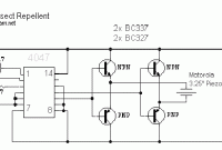
This insect repellent circuit will repel insects such as mosquitoes, flies and cockroaches from your home or yard effectively. circuit uses a specific frequency to […]
Tone Detector / Sound Activated Switch
The following circuit diagrams are tone detector circuit diagrams which also known as sound activated switch circuit. Actually, these circuits? use microntroller for switching because […]
Mini Voice Operated Relay
This is the circuit diagram of a voice operated relay. It similar with sound activation switch circuit which will turn on and turn off (connect […]


