The following diagram is the FM transmitter circuit with FM transmision up to 4W. Voltage supply for this circuit is 12-16V with current consumption of 100-400mA. This circuit works with frequency of emission range of 88-108MHz. Transistor 2N2219 used as the main signal amplifier.
4 Watts FM Transmitter circuit design:
Components List:
R1, R2 = 10K Ohm (1/4 W)
R3 = 47 Ohm (1/4 W)
C1, C2 = 1nF
C3 = 4,7uF/16V
C4, C7, C8 = 0~45pF trimmer
C5, C6 = 10pF
C9 = 100nF
T1, T2 = 2N2219
ANT = Simple dipole l/2.
MIC IN = Microphone dynamic or other type. (It can also connected to a cassette player unit)
Inductor (L) specifications:
L1 = 4 turns, 7mm diameter *
L3 = 3 turns, 7mm diameter *
L4 = 5 turns, 7mm diameter *
L2 = RFC (resistance 1 MOhm with wrapped around her inductor of enough coils from fine isolated wire. Scratch of utmost inductor and you stick in utmost the resistance making thus a parallel L-r circuit.)
* The inductors is air from wire of coaxial 75W or other 1mm roughly.
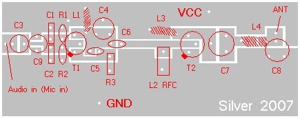
Component Placement:
PCB Layout:
Download?2N2219 datasheet PDF document for 4 watts FM transmitter circuit reference:
Guitar Synthesizer Schematic Diagram In this post, we provide a collection of schematic diagrams of…
Handy Talky Schematic Diagram This is an old electronic scheme of the Handy Talky (HT)…
This is an old or "very old" schematic diagram of birdie tone or sound generator.…
Here is the 200W MOSFET amplifier powered based on four piece of IRFP250N, they are…
This is the 300W RMS stereo power amplifier circuit project. This amplifier is based four…
This is an active stereo tone control circuit using very well known op-amp IC of…
View Comments
IS THIS REALY HAVE 4W POWER AT OUTPUT STAGE YOU CAN USE MRF237 FOR 2W TO 3W
POWER
How do you do L2?
hæhæ 4 watt FM transmitter with 2 transistor 2n2219 I clicked the photo printed board this picture in actual size that I see on the screen? can you send me the correct width and length of the printing table in my email?
Is it really 4W output just oscilator n the Final only? I like it!
I USED 2N 2218,AT OUT PUT STAGE,WHICH GIVES MORE STABILITY.FINALLY GO FOR METAL BOX,TO AVOID INTERFERENCE.