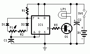
Here’s the?3V lamp brightness controller circuit diagram used to control the brightness of the light bulb. You simply use the two AA or AAA battery to make this circuit works. Example usage of this circuit is to adjust the brightness of images for close-up photo shoot with a digital camera.
IC1 works to generate 150Hz square wave which having a variable duty-cycle. When potensiometer P1 is fully rotated towards D1, the output positive pulses appearing at pin 3 of IC1 are very narrow. Lamp LP1, driven by Q1, is off as the voltage across its leads is too low. When potensiometer P1 is rotated towards R2, the output pulses increase in width, reaching their maximum amplitude when the potentiometer is rotated fully clockwise. In this way the lamp reaches its full brightness.
The lamp LP1 could be one or more 1.5V bulbs wired in parallel. Maximum total output current allowed is about 1A.
R2 limits the output voltage, measured across LP1 leads, to 1.5V. Its actual value is dependent on the total current drawn by the bulb(s) and should be set at full load in order to obtain about 1.5V across the bulb(s) leads when potensiometer P1 is rotated fully clockwise.
Components List:
R1 : 10K
R2 : 47K (See Notes)
R3 : 1K5
P1 : 470K Linear Potentiometer
C1 : 22nF
C2 : 100uF/25V
D1,D2 : 1N4148
IC1 : 7555 or TS555CN CMos Timer IC
Q1 : BD681
LP1 : 1.5V 200mA Bulb
SW1 : SPST Switch
B1 : 3V
Source: redcircuits.com


light bulbs these days are getting replaced by compact fluorescents and LED based ones, original incandescent bulbs are power h _