120W Power Amplifier + Power Supply


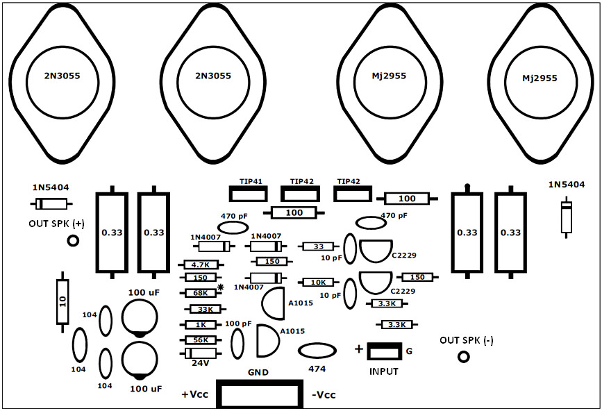
This is 120W power amplifier schematic using TO-3 package complementary transistors, NPN and PNP polarity. The well-known power transistor pair of 2N3055 and MJ2955 used in this circuit.  +/- 50V symmetrical (split/dual polarity) power supply with minimum 3A electric current should be used for maximum performance.

120W Power Amplifier Part List

Transistors

  • 2N3055 (substitution: MJ15003 or 2N3772) : 2
  • MJ2955 (substitution: MJ15004 or 2N3771) : 2
  • TIP42 : 2
  • TIP41 : 1
  • 2SC2229 or 2SC2230 or C1573 : 2
  • A1015 or A872 or A733 : 2

Capacitors

  • 100uF/50V electrolytic capacitor: 2
  • 470nF (474) nonpolar polyester capacitor: 1
  • 100pF (101) nonpolar ceramic capacitor : 2
  • 470pF (471) nonpolar ceramic capacitor : 2
  • 10pF nonpolar ceramic capacitor : 2
  • 100nF (104) 100V nonpolar polyester capacitor : 2

Resistors

  • 0.33 Ω (5W) : 4
  • 10 Ω to (1W) – brown, black, black : 1
  • 100 Ω (1W) – brown, black, brown : 2
  • 33 Ω (1/4W) – orange, orange, black : 1
  • 150 Ω (1/4W) – brown, green, brown : 3
  • 10KΩ (1/4W) - brown, black, orange : 1
  • 1KΩ (1/4W) - brown, black, red : 1
  • 4.7KΩ (1W) - yellow, violet, red : 1
  • 68KΩ (1/4W) - blue, gray, orange : 1
  • 56KΩ (1/4W) - green, blue, orange : 1
  • 33KΩ (1/4W) – orange, orange, orange : 1
  • 3.3KΩ (1/4W) – orange, orange, red : 2

Diodes

  • 3A Diode 1N5404 : 2
  • 1A Diode 1N4007 : 3
  • Zener diodes between 20 and 24 volts : 1

Others

  • 3A fuse
  • small 3-pin (GP) connector
  • large 6-pin connector (Molex)
  • aluminum heatsink
  • potentiometer of 20K if you want to add volume control

120W Power Amplifier PCB Layout Design

Bottom PCB Layout (Copper)

Top PCB Layout and Component Placement

How to mount the transistors to the aluminium heatsink, see below image:

The points are: prevent circuit shortage, use proper isolator and use thermal compound for maximum heat spreading to the heatsink. Use mica between the transistor and the heatsink.

Power Supply Circuit for 120W Power Amplifier

Power Supply Bottom PCB Layout

Power Supply Top PCB Design

Power Supply Part List

  • Transformer for the mono amplifier should be 35 + 35 volts AC with a minimum of 3 amps. If the stereo channel, the amperage should be doubled.
  • Capacitors of 4700 uF/63V: 4
  • Diode bridge (rectifier) ​​of 15 Amps: 1

120W Power Amplifier Wiring Connection

This is how to connect the amplifier module to the speaker, power supply and audio input. And connect the power supply module to the transformer.

circuit diagram

View Comments

Recent Posts

Guitar Synthesizer Schematic Diagram Collection

Guitar Synthesizer Schematic Diagram In this post, we provide a collection of schematic diagrams of…

54 years ago

Handy Talky HT DIY Schematic Diagram

Handy Talky Schematic Diagram This is an old electronic scheme of the Handy Talky (HT)…

54 years ago

Doorbell Ringer Birdie Tone

This is an old or "very old" schematic diagram of birdie tone or sound generator.…

54 years ago

200W MOSFET Amplifier based IRFP250N

Here is the 200W MOSFET amplifier powered based on four piece of IRFP250N, they are…

54 years ago

300W RMS Stereo Power Amplifier based IC TDA7294

This is the 300W RMS stereo power amplifier circuit project. This amplifier is based four…

54 years ago

Stereo Tone Control with Line In + Microphone Mixer

This is an active stereo tone control circuit using very well known op-amp IC of…

54 years ago